
Detail Text Description
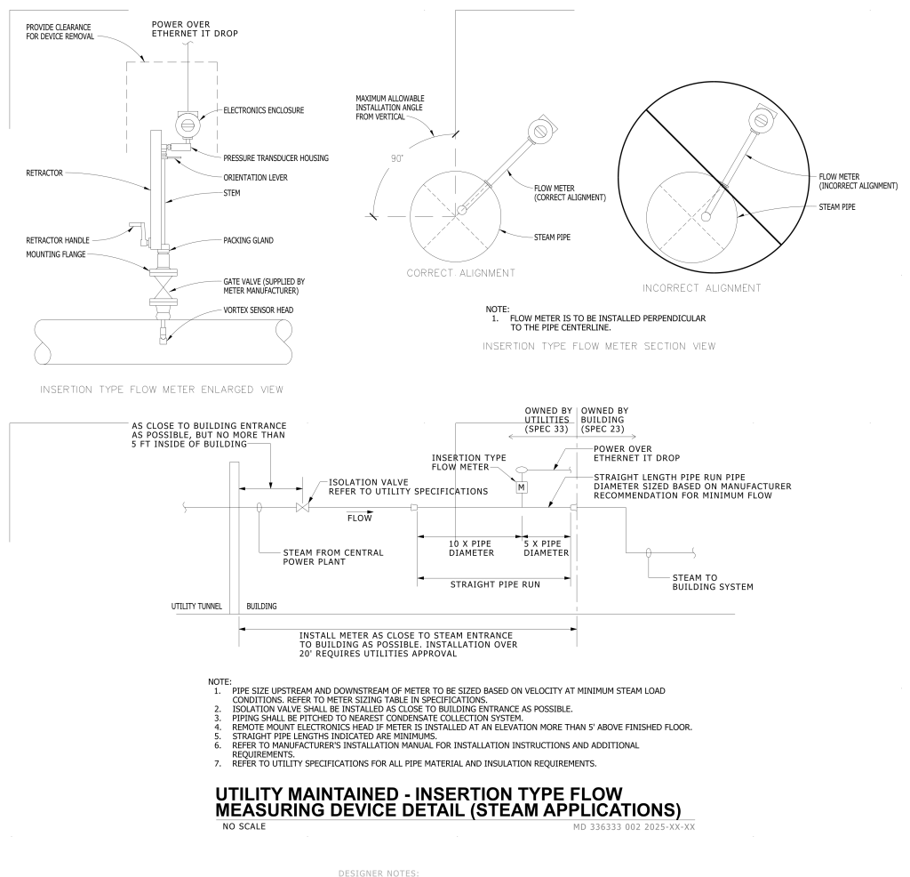
A detailed technical diagram illustrating the installation and alignment of an insertion type flow meter for steam applications. At the top left, an enlarged view shows the assembly of the flow meter, including components such as the electronics enclosure, pressure transducer housing, orientation lever, and vortex sensor head. The flow meter is installed above a steam pipe, with labels indicating various parts like the retractor, retractor handle, mounting flange, and gate valve.
To the right, there are two circular diagrams side by side. The left diagram indicates the correct alignment of the flow meter with max allowable 90-degree from vertical. The right diagram shows an incorrect alignment with the flow meter misaligned in the steam pipe.
Below these diagrams, a larger section provides a flow schematic showing the position of the flow meter in relation to a steam power plant and a building system. The diagram includes labels for various components such as isolation valves, pipe diameters, and specified distances for installation. Text notes provide further installation instructions and specifications.
Additional Formats
Additional formats provided for print or third party applications:
