
Detail Text Description
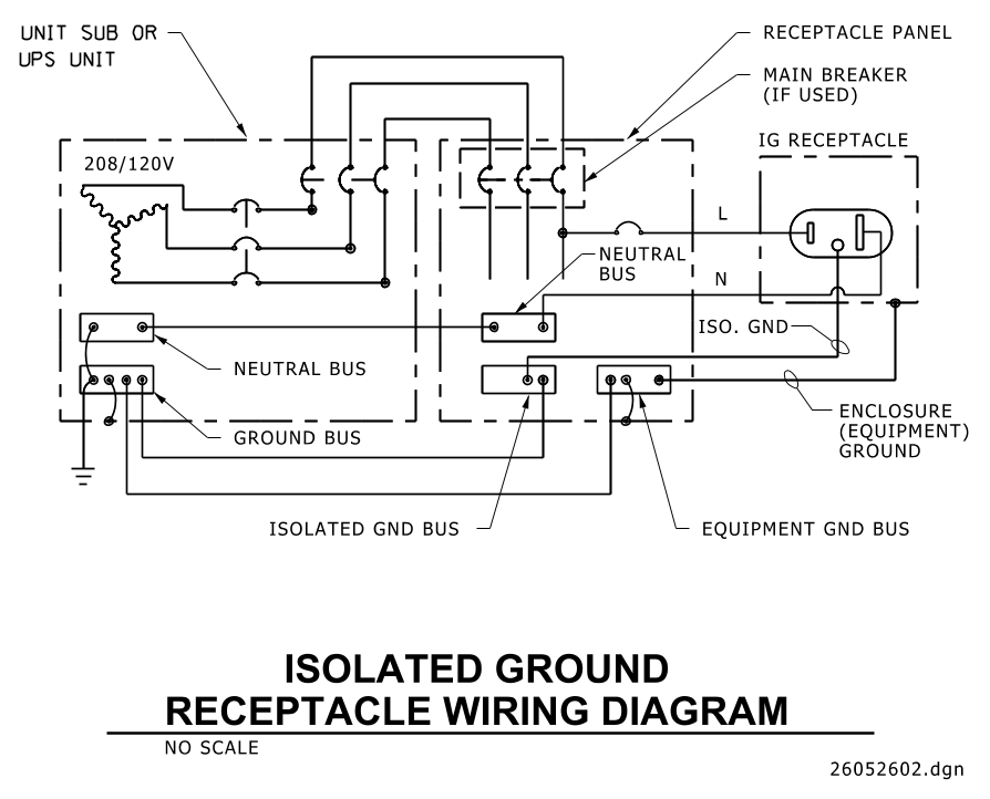
An isolated ground receptacle wiring diagram. The diagram is a schematic representation illustrating the connections between various electrical components. At the top left, there is a label for a “UNIT SUB OR UPS UNIT” connected to a box labeled “208/120V” which leads to a transformer. The lines from these components connect to a “NEUTRAL BUS” and a “GROUND BUS” located on the left side. These buses are connected through solid lines to an “ISOLATED GND BUS” and an “EQUIPMENT GND BUS” on the right side. The right side of the diagram shows a “RECEPTACLE PANEL” with lines leading to an “IG RECEPTACLE,” marked with “L” and “N,” indicating line and neutral connections. The panel is connected to a “MAIN BREAKER (IF USED)” and an “ENCLOSURE (EQUIPMENT) GROUND” labeled line. The layout uses dashed lines for enclosure outlines and solid lines for electrical connections. The bottom section of the diagram includes the title “ISOLATED GROUND RECEPTACLE WIRING DIAGRAM” and notes “NO SCALE.”
Additional Formats
Additional formats provided for print or third party applications:
