
Detail Text Description
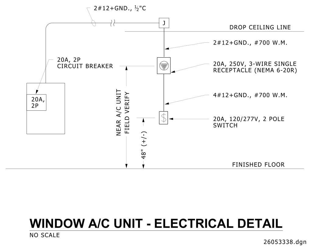
An electrical schematic for a window air conditioning unit. It features a series of lines and symbols representing electrical connections and components. At the top, there is a line labeled “2#12+GND., ½”C” which feeds into a junction box labeled “J” above with the “DROP CEILING LINE.” To the left, there’s a box labeled “20A, 2P CIRCUIT BREAKER,” linked by a curved line to the junction box. Below the junction, a trident symbol is labeled “20A, 250V, 3-WIRE SINGLE RECEPTACLE (NEMA 6-20R).” Junction box is connected to receptacle with 2#12+GND., #700 W.M. Receptacle is connected to 20A, 120/277V 2 Pole Switch with 4#12+GND., *700 W.M. Vertical midpoint of Receptacle is to be field verified that it is located near the A/C unit. Center of Switch is to be approximately 48″ above floor. Additionally, two lines descend from the trident. One is labeled “4#12+GND., #700 W.M.,” while the second ends at a dollar sign symbol, labeled “20A, 120/277V, 2 POLE SWITCH.” The distance between the trident and switch is marked as “48” (+ / -)” from the “NEAR A/C UNIT FIELD VERIFY” to the “FINISHED FLOOR” line. At the bottom of the image, a bold label reads “WINDOW A/C UNIT – ELECTRICAL DETAIL,” with “NO SCALE” and “26053338.dgn” underneath.
Additional Formats
Additional formats provided for print or third party applications:
