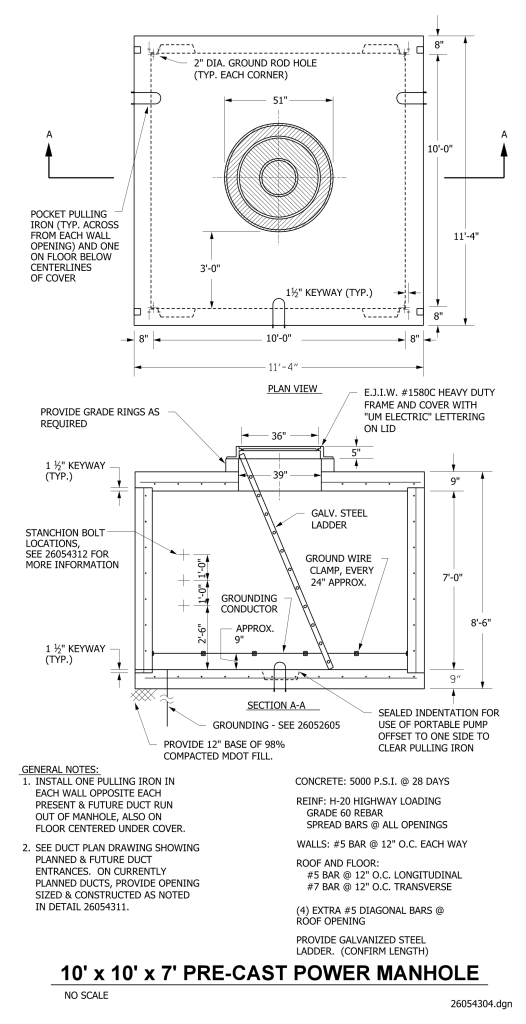
An engineering drawing of a 10’ x 10’ x 7’ pre-cast power manhole. The drawing is divided into a plan view and a section view labeled A-A. In the plan view, the dimensions of the manhole are indicated with arrows and measurements such as a 10-foot square layout. Each corner has a 2-inch diameter ground rod hole, with pulling irons across from each wall opening. A 50-inch diameter manhole frame and cover assembly in the center, with associated dimensions marked.
The section view shows the internal structure and components, such as a galvanized steel ladder and grounding conductor. Dimensions are specified. The section includes notes about the placement of grounding conductors and ground wire clamps. Additional technical details include reinforcing bar specifications and installation notes.
Additional Formats
Additional formats provided for print or third party applications: