
Detail Text Description
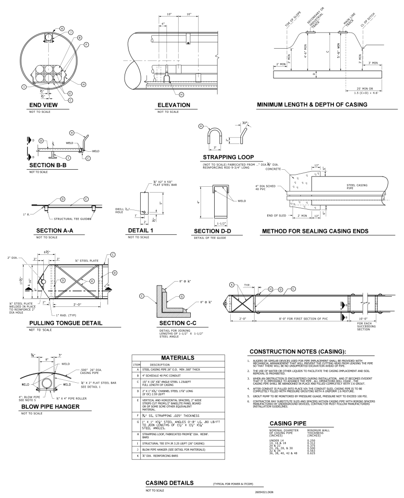
A detailed engineering drawing titled “Casing Details (Typical for Power and Fiber)” showing various views and sections of a steel casing pipe structure. In the top left, the “End View” displays a cross-section of a large diameter pipe with multiple smaller pipes inside. To the right, the “Elevation” view provides a side perspective of the casing, with dimensions indicating overall length and diameter. The “Minimum Length & Depth of Casing” section outlines specific size requirements with measurements. Various smaller drawings present detailed layouts, such as “Section B-B,” “Section A-A,” “Detail 1,” “Section D-D,” and others, focusing on welds, strapping loops, and sealing methods. Each section provides dimensions and materials like steel plates and angles. The lower portion contains a table titled “Materials” listing items necessary for construction with specific descriptions. Another section titled “Construction Notes (Casing)” includes numbered guidelines for assembly. The “Blow Pipe Hanger” and “Pulling Tongue Detail” provide additional structural specifics. The drawing is highly technical, filled with measurements, dimensions, and notations, and is marked “Not to Scale.”
Additional Formats
Additional formats provided for print or third party applications:
