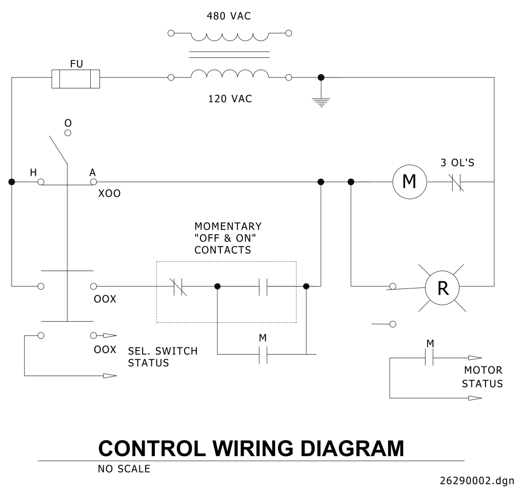
A control wiring diagram, illustrating a basic electrical control circuit. At the top, alternating current (AC) power sources are indicated, labeled with “480 VAC” and “120 VAC,” connected by lines representing wires. A fuse (labeled “FU”) is included in the circuit, positioned before the 120 VAC power split. Ground symbols are present, indicating connections to the earth. The diagram includes various labeled components such as “M” for motor, “R” for relay, and three “OL’s” likely referencing overloads. There are several schematic symbols for switches and momentary contacts, with labels such as “XOO,” “OOX,” and “SEL. SWITCH STATUS.” Text boxes describe connections to momentary “OFF & ON” contacts and the status of the motor. The bottom of the diagram is textually marked “CONTROL WIRING DIAGRAM,” with an additional note “NO SCALE” and a reference identifier “2629002.dgn.”
Additional Formats
Additional formats provided for print or third party applications: