
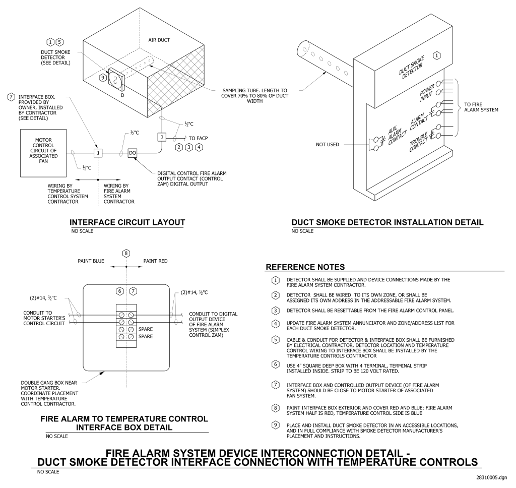
Detail Text Description
The interconnection layout of a fire alarm system device used in duct smoke detector interface connections with temperature controls. In the top left, there is an “Interface Circuit Layout” showing a 3D diagram of an air duct with a sampling tube extending across it. Various connection lines are labeled, showing wiring paths for temperature control, fire alarm system, and to the fire alarm control panel. Below this, the “Fire Alarm to Temperature Control Interface Box Detail” displays a practical setup for wiring two parts, with specific sections painted blue and red.
On the right, a “Duct Smoke Detector Installation Detail” diagram shows a side view of a rectangular duct smoke detector with labeled inputs and outputs, including power input and alarm contact points.
A section titled “Reference Notes” lists specific installation and connection guidelines, including zones, system address assignments, and the color coding for paint on interface box exteriors.
Additional Formats
Additional formats provided for print or third party applications:
