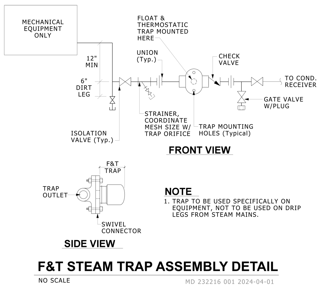
A technical diagram illustrating the “F&T Steam Trap Assembly Detail,” with both front and side views included. The diagram features clear labels and directional arrows indicating parts and connections.
In the front view, starting on the left, there’s a box labeled “MECHANICAL EQUIPMENT ONLY” with a pipe extending right. A 12″ inch min pipe drop section leads to a 6″ inch dirt leg. To the right, a pipe with a series of fittings which includes an isolation valve, a strainer, a union, the float & thermostatic trap,check valve, a union, and a gate valve, leading to a condenser receiver. The float and thermostatic trap is prominently mounted in this section with an indication of trap mounting holes for setup.
The side view shows the F&T trap, illustrating a trap outlet, swivel connector, and parts labeled for orientation like the trap body.
Additional Formats
Additional formats provided for print or third party applications: