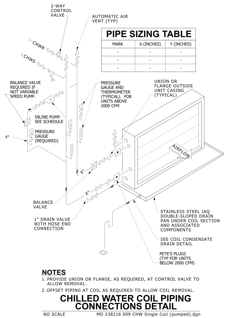
A detailed technical diagram of chilled water coil piping connections. At the top left, components such as ball valve, strainer, automatic air vent, and pressure guage are illustrated with the incoming CHWS pipe. The diagram includes a ball valve and petes plug for the pipe into the chilled water coils. The pipe leaving the coil include a petes plug, a ball valve, balance valve, pressure and temperature gauges. The diagram inlcudes labels for various elements like the inline pump on a bypass loop.This CHWR pipe continues with the automatic air vent and control valve at the top left. At the top right there is a PIPE SIZING TABLE is included, in case there are several different size coils with various columns that include MARK, X, and Y for the different pipe sizes. There are notes included at the bottom regarding offset and flange provisions for coil removal.
Additional Formats
Additional formats provided for print or third party applications: