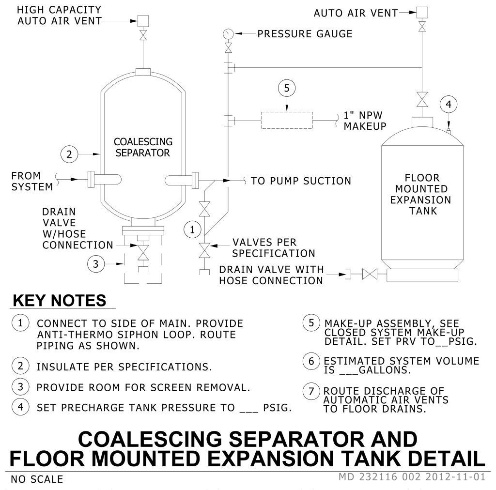
A detailed diagram showing the layout and components of a coalescing separator connected to a floor-mounted expansion tank. On the left, there is a vertically oriented oval-shaped coalescing separator. It includes connections labeled “From System” and “To Pump Suction,” along with a “Drain Valve w/Hose Connection” at the bottom. Arrows indicate flow directions. The separator features a high capacity auto air vent at the top.
To the right, connected by a series of pipes, is a cylindrical floor-mounted expansion tank. This tank has a label reading “1” NPW Makeup,” with lines leading to a pressure gauge and an auto air vent. The diagram is annotated with numbered sections corresponding to key notes, which provide specific instructions and specifications for installation.
Additional Formats
Additional formats provided for print or third party applications: