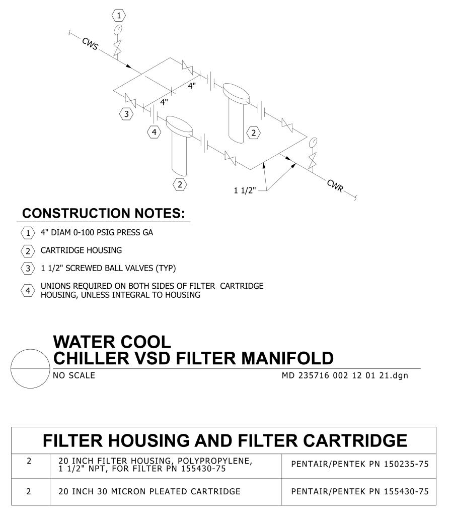
A technical drawing of a water cooling chiller VSD filter manifold system. The diagram includes a layout of pipes and components connected by straight sections and valves. Two prominent cylindrical cartridge housings are located between unions required on either side. Arrows indicate flow direction labeled as “CWS” and “CWR.” The image contains labels for components such as a 4-inch diameter pressure gauge, cartridge housings, and 1.5-inch screwed ball valves. Construction notes detail specifications and requirements for the setup.
Additional Formats
Additional formats provided for print or third party applications: