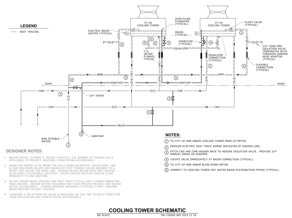
A detailed schematic diagram of a cooling tower system. It features interconnected piping systems, depicted with solid and dashed lines representing various flows and connections. The diagram includes components like cooling towers, electric basin heaters, overflow standpipes, and float valves. Arrows indicate the direction of flow through the system. Several numbered circles are linked to notes explaining specific parts of the system. Labels such as “CWR,” “NPW,” and “SANITARY” identify different pipelines and functions. There is a legend indicating heat tracing, and designer notes providing additional guidance on system adjustments and considerations.
Additional Formats
Additional formats provided for print or third party applications: