
Detail Text Description
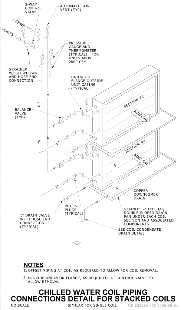
A technical diagram illustrating the detailed connections for chilled water coil piping, specifically for stacked coils. The diagram features a three-dimensional representation of a dual-level coil system labeled as Section #1 and Section #2, indicating the direction of airflow with arrows. Various components are annotated, including a 2-way control valve, automatic air vent (typical), pressure gauge, and thermometer for units above 2000 CFM. It shows the piping connections with markings for CHWR (Chilled Water Return) and CHWS (Chilled Water Supply). The design includes a balance valve, strainers with blowdown and hose end connections, and union or flange outside unit casing. At the bottom of each coil, a 1-inch drain valve is noted, along with Pete’s plugs and copper downcomer drain. The stainless steel IAQ double-sloped drain pan is mentioned beneath each coil section, with a direction to see coil condensate drain detail. Notes at the bottom stress offset piping at the coil for removal and providing union or flange at control valves for easy removal.
Additional Formats
Additional formats provided for print or third party applications:
