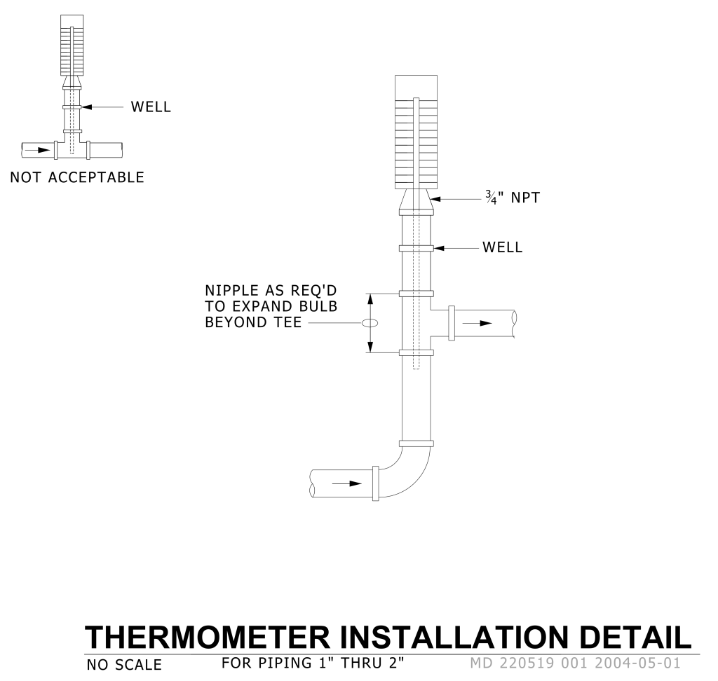
A technical diagram labeled “Thermometer Installation Detail.” It shows two illustrations of thermometer installation in piping systems. On the left, a smaller diagram marked “Not Acceptable” illustrates a thermometer inserted improperly, with an arrow pointing to a segment labeled “Well.” On the right, a larger diagram shows the correct installation, with a thermometer attached at a ¾” NPT fitting and a pipe labeled “Well.” It includes arrows and annotations, indicating where a nipple is required to extend the bulb beyond the tee.
Additional Formats
Additional formats provided for print or third party applications: