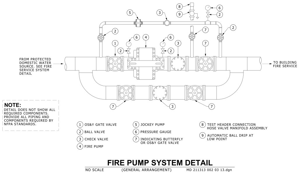
A technical schematic of a fire pump system, illustrating the layout and components in a line drawing. Central to the diagram is a series of connected pipes, valves, and pumps, labeled numerically to correspond with a legend below. The schematic starts with an inlet on the left labeled “FROM PROTECTED DOMESTIC WATER SOURCE” and ends with an outlet on the right labeled “TO BUILDING FIRE SERVICE.” Key components include several OS&Y gate valves, ball valves, check valves, and a prominently placed fire pump at the center. Various additional elements such as jockey pump, test header, and automatic ball drip are indicated in the design. Pipes of various lengths connect these components, forming a connected loop structure. A note at the bottom left emphasizes that the detail does not showcase all required components, and compliance with NFPA standards is required.
Additional Formats
Additional formats provided for print or third party applications: