
Detail Text Description
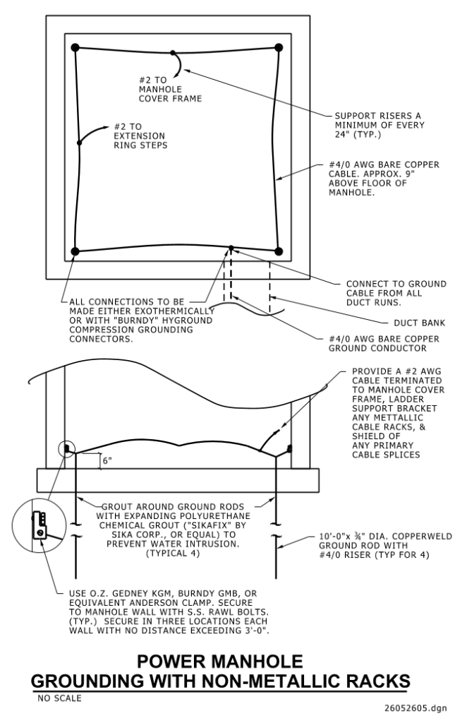
A technical diagram illustrating the grounding of a power manhole with non-metallic racks. The diagram displays a plan view of a manhole with key components and annotations. A square shape represents the manhole, outlined with a solid line and labeled with “#2 to manhole cover frame” and “#2 to extension ring steps.” There are support risers labeled “Support Risers A Minimum of Every 24” (Typ.)” surrounding the interior.
Inside the square, a line labeled “#4/0 AWG Bare Copper Cable Approx. 9” Above Floor of Manhole” runs across the diagram. Dashed lines indicate the connection to a duct bank and another line labeled “#4/0 AWG Bare Copper Ground Conductor.”
The diagram further features details of connections and equipment, such as “All Connections To Be Made Either Exothermically or With ‘Burndy’ Hyground Compression Grounding Connectors.” Additional notes describe components like “10′-0″ x 3/8″ Dia. Copperweld Ground Rod with #4/0 Riser (Typ for 4)” and specific materials for sealing, such as “Grout Around Ground Rods with Expanding Polyurethane Chemical Grout (‘Sikaflex’ By Sika Corp., or Equal) to Prevent Water Intrusion (Typical 4).”
The bottom image shows a cross section and the method for securing parts, “Use O.Z. Gedney KGM, Burndy GMB, or Equivalent Anderson Clamp. Secure to Manhole Wall with S.S. Rawl Bolts (Typ.). Secure in Three Locations Each Wall with No Distance Exceeding 3′-0.”
Additional Formats
Additional formats provided for print or third party applications:
