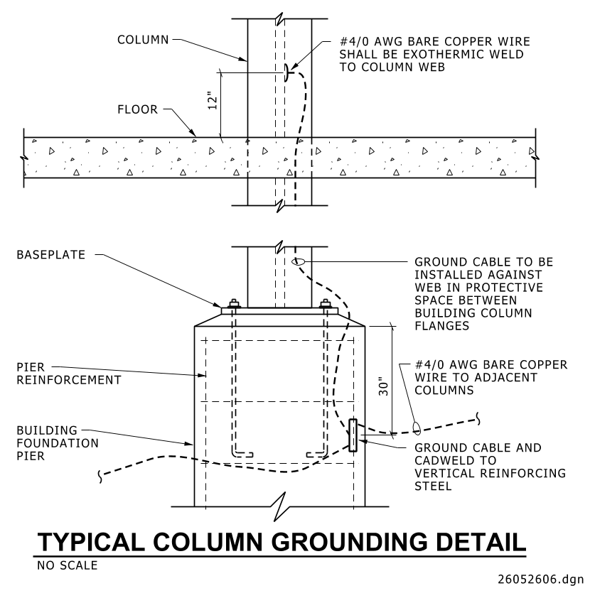
A technical drawing illustrating a typical column grounding detail. It is divided into two sections to show different components of a column grounding system. The top section depicts a cross-section of a floor with a column emerging through it. The floor is marked with a speckled texture, indicating the concrete surface, with a dimension of “12 IN” extending vertically on the column. The drawing specifies a #4/0 AWG bare copper wire exothermically welded to the column web.
The bottom section shows a more detailed view of the column grounding setup. It includes a baseplate, pier reinforcement, and the building foundation pier. A dashed line indicates the path of a ground cable installed in the protective space between building column flanges. A #4/0 AWG bare copper wire connects to adjacent columns. Additionally, the ground cable links to vertical reinforcing steel, with a dimension labeled “30 IN” extending next to the column.
Additional Formats
Additional formats provided for print or third party applications: