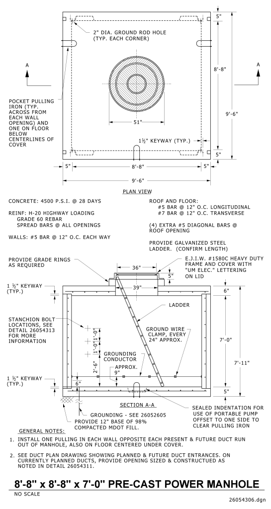
A technical drawing of a pre-cast power manhole structure, presented in two main views: a plan view and a sectional view labeled “Section A-A.” The plan view is a top-down representation showing a square layout measuring 9′-6″ x 9′-6″, with ground rod holes located in each corner. Key measurements and specifications are indicated around the drawing, such as a 51″ circular opening with a 1½” keyway. Labels indicate elements like pocket pulling iron and dimensions of various components. The sectional view displays the internal structure of the manhole, including a galvanized steel ladder, grounding wire clamp, and specifics on the concrete composition. Text around the drawing provides concrete specifications, reinforcement details, and roof and floor construction notes. General notes and recommendations for installation are listed at the bottom of the image.
Additional Formats
Additional formats provided for print or third party applications: