
Detail Text Description
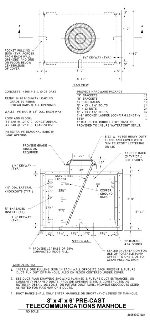
A detailed engineering drawing of a pre-cast telecommunications manhole. The drawing includes a plan view and section view labeled “A-A.” In the plan view, the manhole is a rectangular structure with labeled interior dimensions: 8 feet by 4 feet with a 4-foot clearance and 5-inch border on either side. Central to the plan view is a circular manhole cover labeled with a “1½” keyway (typical).” A sectional arrow labeled “A” is shown on both sides, indicating orientation. Several features, such as “pocket pulling iron” and “spread bars” are annotated, emphasizing placement and positioning.
The section view “A-A” illustrates the manhole’s interior with detailed dimensions. It includes a galvanized steel ladder, copper ground bars, threaded inserts, lateral knockouts, and base specifications for compacted fill. The tower frame and cover detail notes “E.J.I.W. #1805 Heavy Duty Frame and Cover with ‘UM Telecom’ Lettering on Lid.”
Detailed notes and instructions are provided, including materials specifications (“Concrete: 4500 P.S.I. @ 28 Days”) and reinforcement details (“Reinf: H-20 Highway Loading”). Additional general notes offer guidelines on placement and design considerations for duct banks and duct entrances.
Additional Formats
Additional formats provided for print or third party applications:
