
Detail Text Description
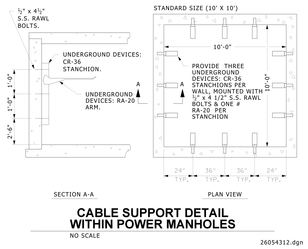
Technical drawings detailing a cable support system within power manholes. On the left side, a sectional view illustrates the assembly of the system, labeled “SECTION A-A.” This view shows a vertical spacing betwen bolts of 1′-0″ and the first bolt at 2′-6″ above the bottom of the manhole. The sectional drawing provides measurements indicating a vertical spacing of 1′-0″ and 2′-6″.
On the right, a plan view is presented, labeled “PLAN VIEW,” showing a top-down layout of a 10′ x 10′ square space with stanchions evenly distributed along the walls. The text describes the standard size as “10′-0″ x 10′-0” and instructs, “PROVIDE THREE UNDERGROUND DEVICES: CR-36 STANCHIONS PER WALL, MOUNTED WITH ½” x 4 1/2” S.S. RAWL BOLTS & ONE # RA-20 PER STANCHION.” The drawing includes evenly spaced measurements for the stanchions, with 36″ between stanchions and 24″ from the manhole wall to the first stanchion.
At the bottom, the text reads “CABLE SUPPORT DETAIL WITHIN POWER MANHOLES,” followed by “NO SCALE.” The drawing is marked with the number “26054312.dgn.”
Additional Formats
Additional formats provided for print or third party applications:
