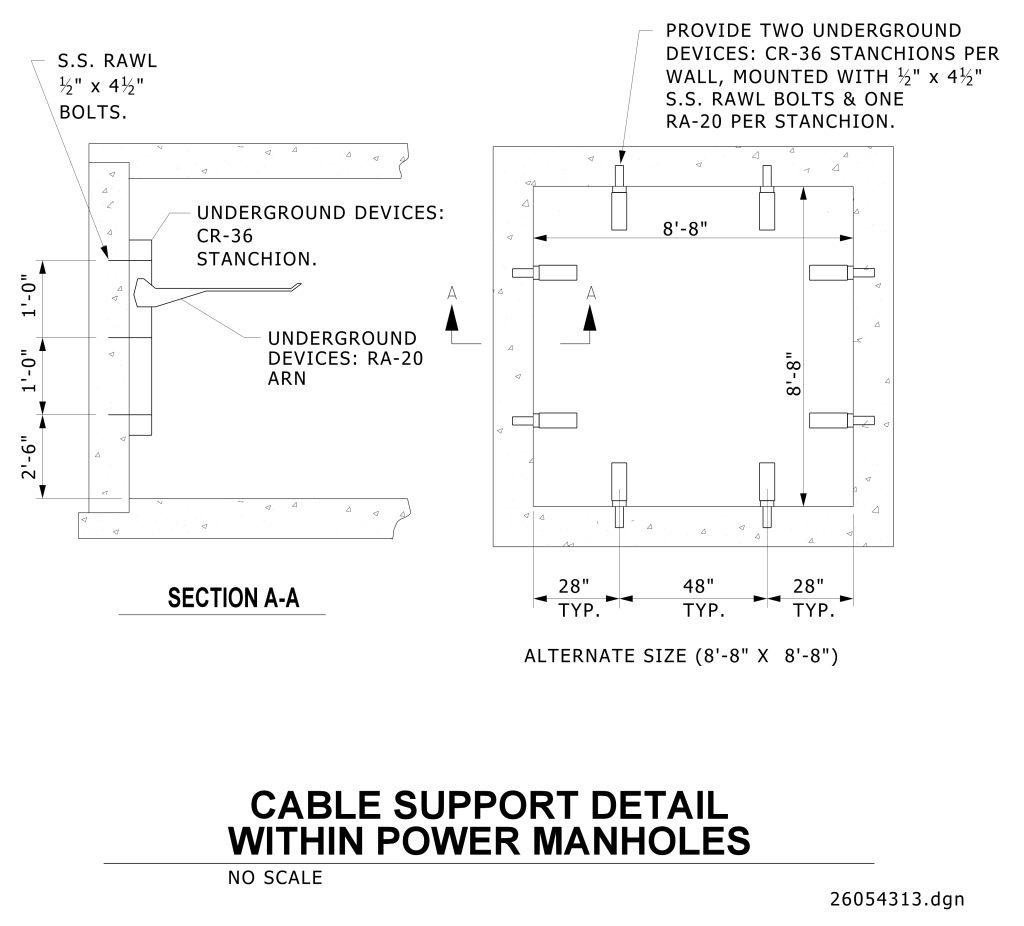
A technical drawing detailing cable support structures within power manholes. It consists of two main drawings, labeled “Section A-A” and a plan view labeled “Alternate Size (8′-8″ X 8′-8″)”. The left side of the image, Section A-A, shows a side view cross-section with a vertical spacing betwen bolts of 1′-0″ and the first bolt at 2′-6″ above the bottom of the manhole. Stainless Steel (S.S.) Rawl bolts measuring ½” x 4½” are indicated. Two underground devices, labeled CR-36 and RA-20, are depicted. The right side shows a top-down layout of an 8′-8″ x 8′ x 8″ square space with stanchions evenly distributed along the walls. Stanchions are spaced 48″ apart and 28″ from the manhole walls on each side. Annotations describe the stanchion mounting details and device placements. The entire diagram is labeled “Cable Support Detail Within Power Manholes” at the bottom, accompanied by “NO SCALE” and file number “26054313.dgn.”
Additional Formats
Additional formats provided for print or third party applications: