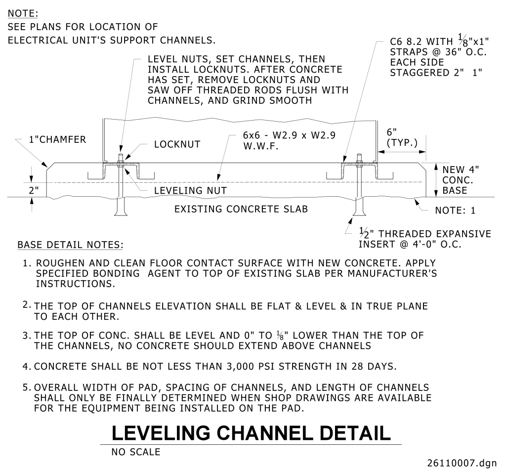
A detailed technical drawing labeled “Leveling Channel Detail” with no scale indicated. It shows a cross-section view of the leveling mechanism for a concrete base intended to support electrical units. The left side of the diagram features a threaded rod with a leveling nut placed over an existing concrete slab and a new channel being supported on top of the nut. There is a locknut above the channel, and a 1-inch chamfer is noted. On the right side, similar details are mirrored with measurements specifying new concrete base height and other details such as C6 8.2 channels with straps. Various notes indicate the use of leveling nuts and locknuts, emphasizing proper setup and concrete strength requirements. The drawing also includes specific measurement conventions, such as 6 inches typical width for components, the use of welded wire fabric (6×6 – W2.9), and threaded expansive inserts.
Additional Formats
Additional formats provided for print or third party applications: