
Detail Text Description
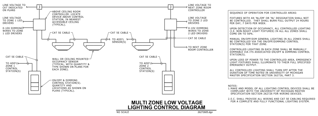
A detailed schematic diagram of a multi-zone low voltage lighting control system. The layout is primarily composed of several interconnected components and labels describing their functions and connections. At the top, various lines indicate “Line Voltage” to different components like the Zone 1 LED drivers, and controllers. Rectangular boxes symbolize room controllers and LED drivers. The paths between these components are primarily connected using CAT 5E cables.
Beneath these, the diagram features symbols depicting sensors. Arrows and lines connect these symbols to the room controllers and control stations. Each component and connection is labeled with specific instructions, such as the typical location or type of cable used.
On the right side, enclosed within a box, is a “Sequence of Operation for Controlled Areas” providing detailed operational guidelines. Below this section, additional notes specify compliance and installation instructions.
The bottom left of the diagram has text reading “Multi Zone Low Voltage Lighting Control Diagram” and the image is marked as “No Scale” with a file name “26272605.dgn” at the bottom right corner.
Additional Formats
Additional formats provided for print or third party applications:
