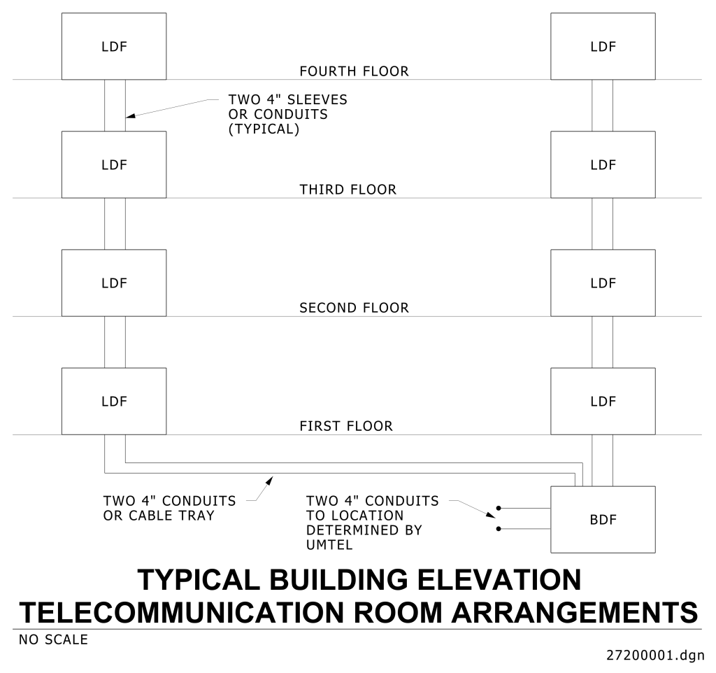
A diagram illustrating the typical building elevation for telecommunication room arrangements. It consists of a vertical sequence of rectangles on both the left and right sides, representing floors of a building. Each rectangle is labeled “LDF” on the first through fourth floors. Connecting lines between the left and right columns of rectangles indicate conduits or pathways. The third floor specifically delineates “Two 4-inch sleeves or conduits (typical).” Below the first floor, there is an additional rectangle labeled “BDF,” connected by lines marked as “Two 4-inch conduits or cable tray” and “Two 4-inch conduits to location determined by UMTEL.” The title at the bottom reads “Typical Building Elevation Telecommunication Room Arrangements,” labeled “No Scale.”
Additional Formats
Additional formats provided for print or third party applications: