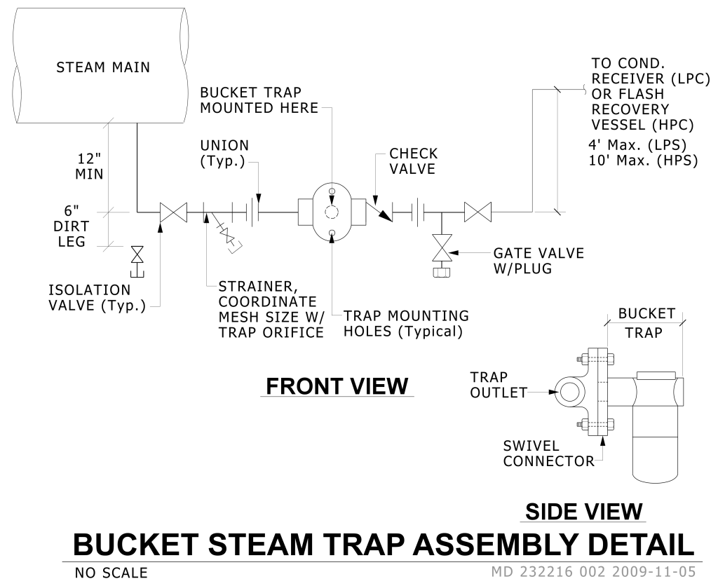
A technical diagram illustrating a bucket steam trap assembly. It is divided into two views: a “Front View” and a “Side View.” The “Front View” displays a horizontal assembly with labeled components such as the “STEAM MAIN,” a 12 min pipe drop section leading to a 6″ dirt leg. Following this, the diagram includes a “STRAINER, COORDINATE MESH SIZE W/ TRAP ORIFICE,” a “UNION (Typ.),” and “CHECK VALVE.” To the right, a pipe with a series of fittings which includes an isolation valve, a strainer, a union, the bucket trap, check valve, a union, and a gate valve, leading to a recovery vessel. The “TO COND. RECEIVER (LPC) OR FLASH RECOVERY VESSEL (HPC)” indicates that the piping leads to another section up to specified maximum distances for “LPS” and “HPS.” Below, the side view shows the “BUCKET TRAP” with parts labeled “TRAP OUTLET” and “SWIVEL CONNECTOR.”
Additional Formats
Additional formats provided for print or third party applications: