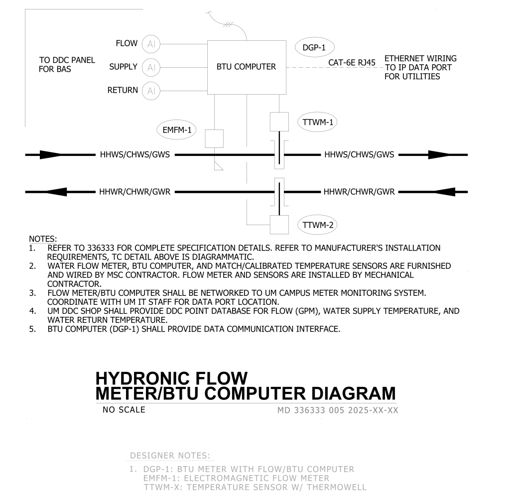
A technical diagram showcasing the layout of a hydronic flow meter and BTU computer system. At the center, a “BTU COMPUTER” is connected to a “DGP-1” via “CAT-6E RJ45” labeled as “ETHERNET WIRING TO IP DATA PORT FOR UTILITIES.” Flow, supply, and return lines marked with “AI” extend from the computer. The “TO DDC PANEL FOR BAS” is marked on the left. Below the BTU computer are connected components “EMFM-1” for electromagnetic flow measurement and “TTWM-1” and “TTWM-2” for temperature sensing with thermowells, connected to arrows labeled “HHWS/CHWS/GWS” and “HHWR/CHWR/GWR,” indicating fluid pathways. The diagram includes notes outlining specifications and installation requirements.
Additional Formats
Additional formats provided for print or third party applications: