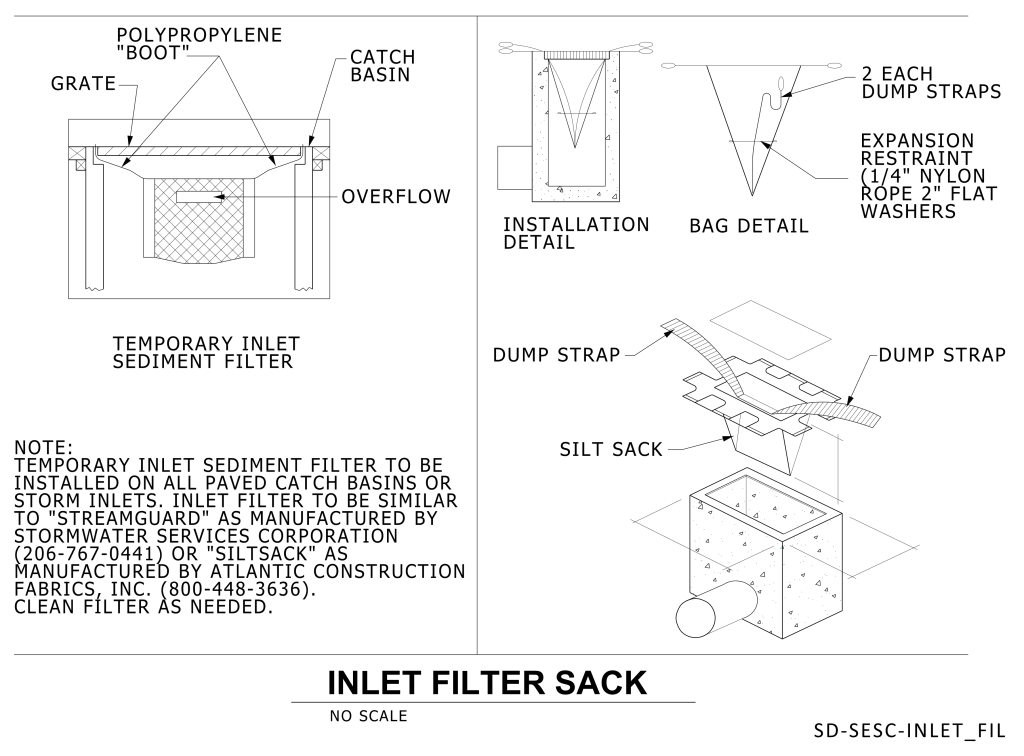
Detail consists of section and axonometric drawing with details of an inlet filter sack. In the top-left is a cross-sectional diagram of a catch basin fitted with a temporary inlet sediment filter, showing the polypropylene “boot,” grate, and overflow components. Directly to the right is a schematic detailing the installation, highlighting positions for dump straps and expansion restraints on the silt sack. Below this, a three-dimensional exploded view illustrates a silt sack installation, with labels denoting the dump strap and the silt sack components. A note in the bottom left corner specifies installation and maintenance instructions.
Additional Formats
Additional formats provided for print or third party applications: