
Detail Text Description
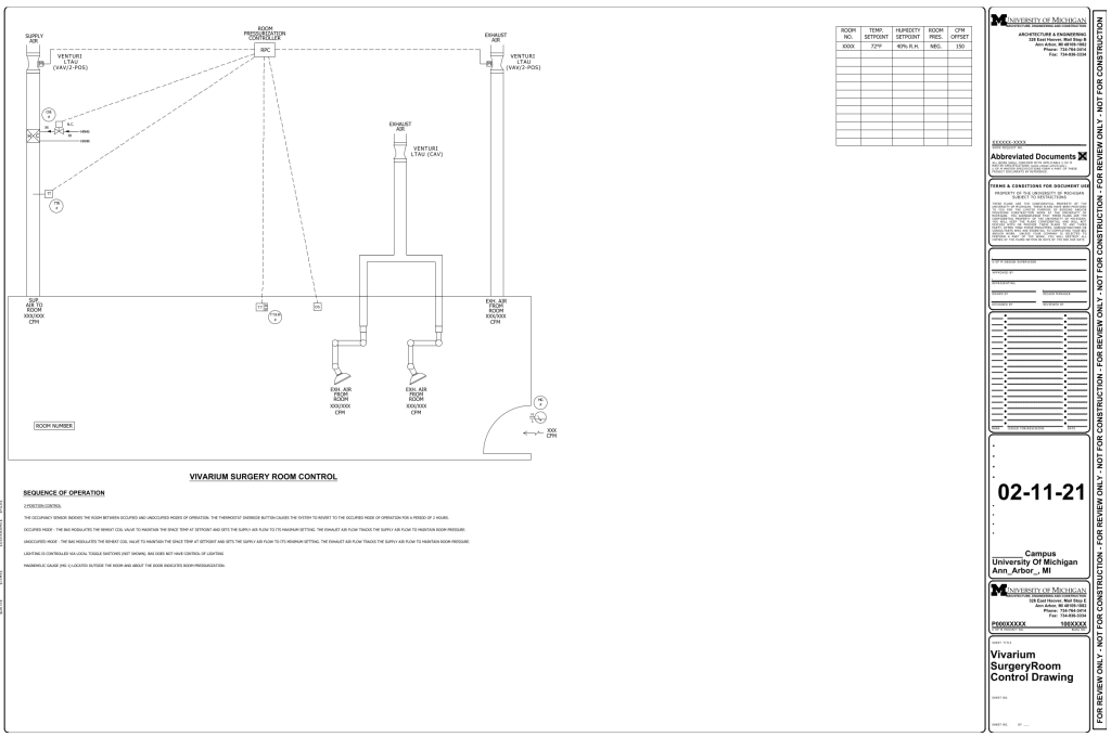
A detailed engineering schematic of a vivarium surgery room’s ventilation control system. It features a schematic layout of a room with various ventilation components such as two venturi valves labeled “SUPPLY” and “EXHAUST” positioned at opposite ends. There are dashed lines connecting components throughout the layout, indicating control wires from various component to a Room Pressurization Controller (PRC). Each venturi valve specifies its position with the notes VAV/2-POS. The drawing includes HVAC symbols and notations such as “RPC”, denoting room pressure controls, and various circular symbols representing sensors and control points. In addition a venturi valve is shown wth two snorkel exahusts. A door is illustrated at the bottom right, marked with a magnehelic pressure gauge and a negative air flow direction arrow. To the lower left section, there is a sequence of operation text detailing modes and functions. There is a grid table at the top right, listing room environmental setting like temperature, humidity, pressure and offset. This was printed on a standard University of Michigan Architecture and Engineering title block dated 02/11/21.
Additional Formats
Additional formats provided for print or third party applications:
