
Detail Text Description
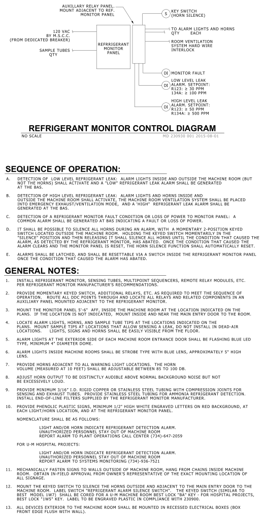
A technical diagram and instruction sheet for a “Refrigerant Monitor Control Diagram.” At the top, there is a line drawing representing the connections of the refrigerant monitor panel, including auxiliary relay panel, key switch, alarm lights and horns, and room ventilation system. Each component has labeled connections indicating specific functions like monitor fault, low and high-level leak alarm setpoints.
The body of the image consists of detailed procedural text. It is divided into two main sections: “Sequence of Operation” and “General Notes.” The “Sequence of Operation” outlines procedures for alarm activations, silencing alarms, and resetting conditions linked to refrigerant leaks or faults. The “General Notes” provide installation instructions, configuration requirements, and specifications on components like alarm lights, horns, and tubing. It contains several numbered points with technical specifications and contacts for alarm systems related to U-M hospital projects.
Additional Formats
Additional formats provided for print or third party applications:
