
Detail Text Description
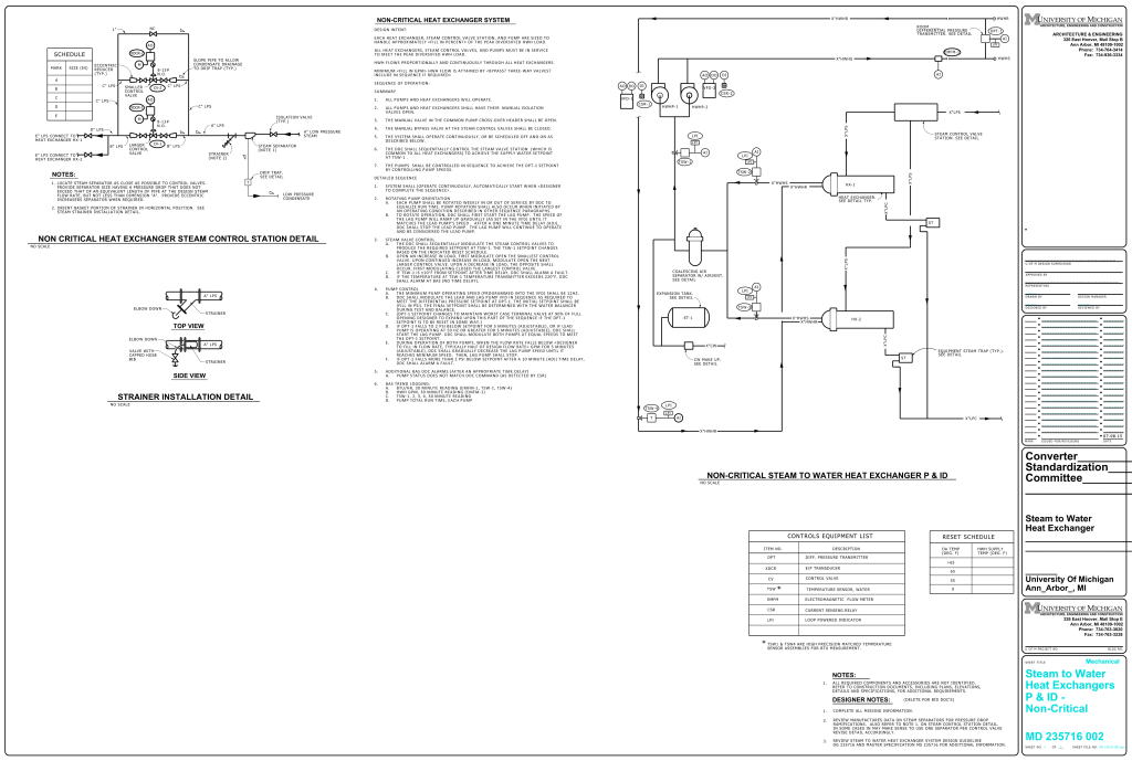
A detailed engineering diagram that depicts a “Non-Critical Steam to Water Heat Exchanger” system. The layout is highly technical, consisting of schematics and annotations. The diagram is divided into several sections, featuring a layout of pipes and equipment interconnected through labeled lines and symbols. On the left side, there is a schematic for the “Non Critical Heat Exchanger Steam Control Station Detail”, illustrating the flow of steam through control valves and strainers. Below it, there’s a strainer installation detail shown in both top and side views, depicting the arrangement of pipes and strainers. The right side displays a more intricate “P&ID” (Piping and Instrumentation Diagram) for the heat exchanger system, indicating various pressure regulating, safety devices. The right side contains a larger schematic illustrating the heat exchanger system’s components, interconnections, and flow directions. The diagram is filled with symbols representing valves, control points, and measurement tools. Several sections have text boxes with instructions, notes, and operational sequences. There is a table labeled “Controls Equipment List” and another section titled “Reset Schedule.” This was printed on a standard University of Michigan Architecture and Engineering title block.
Additional Formats
Additional formats provided for print or third party applications:
