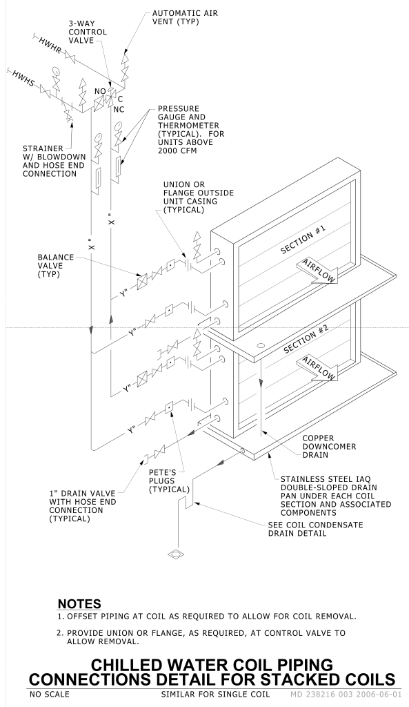
A technical diagram illustrating the piping connections for chilled water coil systems in a stacked configuration. At the top, a 3-way control valve is labeled, connecting to the system’s hot water return (HWHR) and hot water supply (HWHS) lines. An automatic air vent is placed at the junction, marked as typical (TYP). Below this is a strainer with blowdown and hose end connection. A pressure gauge and thermometer setup, indicated for units above 2000 CFM, follows the flow of the piping.
The graphic emphasizes unions or flanges outside the unit casing, described as typical. Two sections, each labeled “SECTION #1” and “SECTION #2,” are included in a perspective view, both with “AIRFLOW” marked by arrows. The diagram also includes balance valves and components identified as “Pete’s Plugs” as common features. The lower portion of the image illustrates a copper downcomer drain and a stainless steel IAQ double-sloped drain pan beneath each coil section.
Additional Formats
Additional formats provided for print or third party applications: