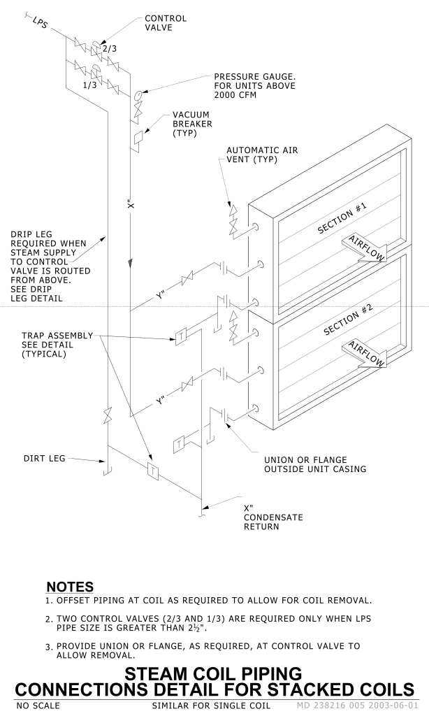
A detailed schematic diagram of steam coil piping connections for stacked coils. At the top left, there are two control valves with two inlets labeled “2/3” and “1/3.” The diagram includes components like a pressure gauge, vacuum breaker, and automatic air vent, labeled as typ (typical). Two main sections labeled “Section #1” and “Section #2” show the airflow direction with arrows. These sections are stacked vertically with details on trap assemblies and connections. The diagram features various piping connections like “Y” connections, dirt leg, and drip leg. Each section is housed in a rectangular casing with a flange or union outside the unit casing. Below, notes provide additional installation guidance and specifications.
Additional Formats
Additional formats provided for print or third party applications: