
Detail Text Description
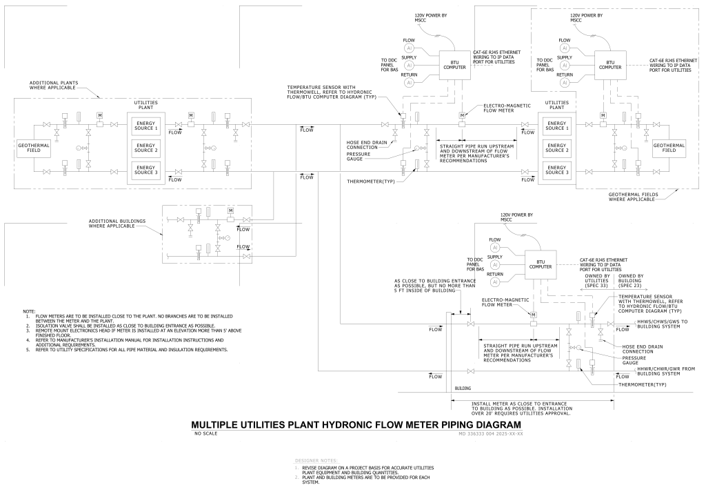
A detailed hydronic flow meter piping diagram for a multiple utilities plant. It is comprised of a network of blocks representing the utilities plant, energy sources, and geothermal fields, interconnected by various lines indicating fluid flow direction. The utility plant is shown with three energy sources, each having associated flow meters (denoted by “M”), valves (depicted by various standard symbols), and sensors including pressure gauges and thermometers. The diagram outlines connections to additional plants and buildings where applicable.
Detailed annotations specify locations for installing equipment such as BTU computers, electromagnetic flow meters, and temperature sensors with thermowells. The flow lines are marked with directional arrows, and additional details like hose end drain connections and straight pipe requirements for flow measurement are noted. Power supply boxes and Ethernet wiring specifications for data transmission are indicated.
There are several notes at the bottom of the diagram, providing installation instructions like flow meter placement and material requirements.
Additional Formats
Additional formats provided for print or third party applications:
