
Detail Text Description
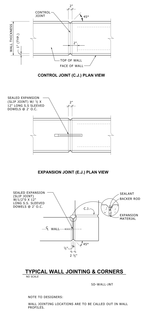
Technical diagrams detailing wall joint designs. At the top, a “Control Joint (C.J.) Plan View” is illustrated. It shows two sections of a wall with a control joint, which has a 2-inch separation and a 45-degree angle, marked with a dimension line for thickness and typical measurements. “Wall Thckness” is variable based on wall construction with labels for the “Top of Wall” and “Face of Wall.”
Below, an “Expansion Joint (E.J.) Plan View” is depicted. This describes an expansion joint with similar wall sections, a 2-inch gap, and stainless steel sleeved dowels marked as “Sealed Expansion (Slip Joint).”
At the bottom, typical corner wall joint shows the joint components like “Sealant,” “Backer Rod,” and “Expansion Material.” Labels such as C.J. indicate control joints, and dimensions highlight specifics like the joint’s width and specific angles.
The drawing is titled “Typical Wall Jointing & Corners,” with a note stating: “Wall jointing locations are to be called out in wall profiles.”
Additional Formats
Additional formats provided for print or third party applications:
