
Detail Text Description
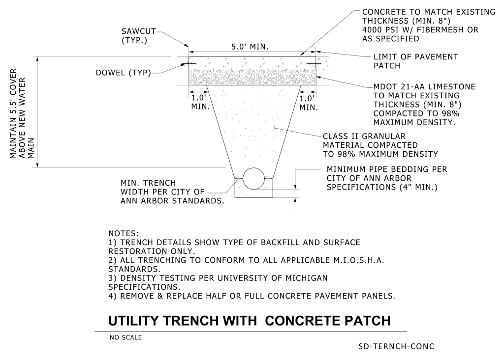
A technical drawing illustrating the cross-section of a utility trench with a concrete patch. At the top, the drawing indicates “SAWCUT (TYP.)” next to a vertical line, with an indication of a minimum 5.0-foot width. Below is a layer marked as “CONCRETE TO MATCH EXISTING THICKNESS (MIN. 8″) 4000 PSI W/ FIBERMESH OR AS SPECIFIED,” with a mention of “LIMIT OF PAVEMENT PATCH.” Beneath this concrete layer, a textured layer is labeled “MDOT 21-AA LIMESTONE TO MATCH EXISTING THICKNESS (MIN. 8″) COMPACTED TO 98% MAXIMUM DENSITY.”
Further below, the drawing shows a triangle shape labeled “CLASS II GRANULAR MATERIAL COMPACTED TO 98% MAXIMUM DENSITY,” with lines extending to it. Within the triangle, a circular shape represents a pipe with the label “MINIMUM PIPE BEDDING PER CITY OF ANN ARBOR SPECIFICATIONS (4″ MIN.).”
Several dimensions are indicated: The concrete patch is shown with a “1.0′ MIN.” distance on each side of the trench, and the label “MAINTAIN 5.5′ COVER ABOVE NEW WATER MAIN” is noted vertically on the left. A line specifies “MIN. TRENCH WIDTH PER CITY OF ANN ARBOR STANDARDS.”
Below the illustration, there are notes regarding trench construction:
- Trench details show type of backfill and surface restoration only.
- All trenching to conform to all applicable M.I.O.S.H.A. standards.
- Density testing per University of Michigan specifications.
- Remove & replace half or full concrete pavement panels.
At the bottom, the title “UTILITY TRENCH WITH CONCRETE PATCH” is centered, with “NO SCALE” and “SD-TERNCH-CONC” text aligned on the bottom left and right respectively.
Additional Formats
Additional formats provided for print or third party applications:
